|
In industry the PLC is the most important automation device because of its role as the brain in running industrial processes. This brain uses a syntax to be able perform tasks in an orderly, sequential manner.
The native language of the PLC is called “ladder logic”. Ladder logic is graphical, in that it can be laid out in a form that resembles a ladder with rails and rungs. Ladder logic diagrams were developed originally from relay-circuit diagrams that were used for electronic circuitry prior to the advent of PLCs. PLC Ladder Simulator is a simulator for the Android operating system with input and output objects that simulate the I/O ports of a real PLC. You can used PLC Ladder Simulator to create ladder-logic diagrams using components from the standard set used in these diagrams.
|

|
IMPORTANT: No refunds for the PRO EDITION will be made beyond 72 hours after its purchase if the problem is compatibility in Arduino mode. The rationale for this is that you can use the free version of PLC Ladder Simulator to test and see if the Arduino is compatible with your version of PLC Ladder Simulator prior to purchasing the PRO version.
DIFERENCES BETWEEN THE FREE AND THE PRO VERSION
The Pro version features compared with the Free version are:
- Arduino Mega board available in Arduino mode.
- Arduino Nano board available in Arduino mode.
- Arduino Due board available in Arduino mode.
- Arduino Pro Mini available in Arduino mode.
- MH-ET LIVE ESP32 DevKit board in Arduino mode.
- NodeMCU V3 LUA ESP8266 board in Arduino mode.
- Export .PLC file for the PC PLC Loader tool (only for the Arduino UNO, Nano and Mega).
- ROL ladder function.
- ROR ladder function.
- SCL ladder function.
- No restriction for counters.
- No restriction for timers.
- No Ads.
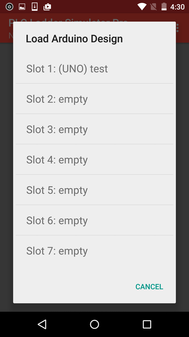
- 10 save slots for keep more designs with slot name customization.
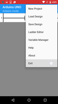
PLC LADDER SIMULATOR HAS FOUR PARTS
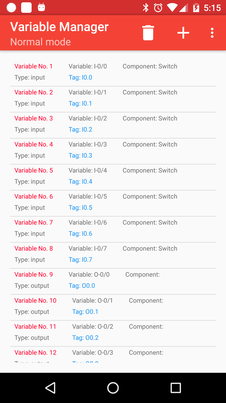
The Variable Manager
|
The Variable Managers allows you to create and describe variables to be used in your ladder-logic diagram.
There are six types of variables:
|
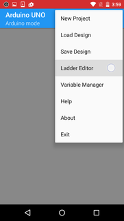
The Ladder Editor
|
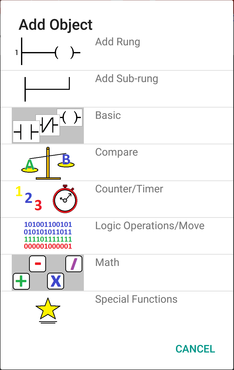
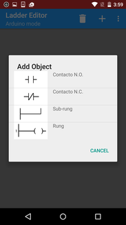
The Ladder Editor is used to create your ladder-logic diagrams. There are tools to add, edit, and delete objects. The component library has 47 objects, such as a rung, a sub-rung, a normally open contact, a normally closed contact, a counter, a timer, etc.
Every rung will have a coil as its output. When a rung is added, the coil is added automatically. You choose the output variable that will be associated with that coil. To add a contact, you must first have added a rung or a sub-rung upon which to add that contact. After indicating that you want to add a contact, you touch the rung or sub-rung to which you want to add it. |
|
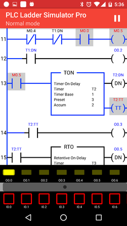
PLC I/O Interface
The PLC I/O Interface appears when the ladder-logic diagram is simulated on your Android device. The ladder-logic diagram appears on the upper part of the screen, the PLC I/O Interface below it. It has in its upper part indicator lights that represent the PLCs output coils. They turn yellow when the associated coil is high. Below them is the row of PLC inputs. You interact with your PLC simulation by pressing the switches or buttons that form the inputs.
If there are more inputs or outputs than can be displayed on the screen, you can slide them back and forth with your finger to see them.
If there are more inputs or outputs than can be displayed on the screen, you can slide them back and forth with your finger to see them.
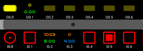
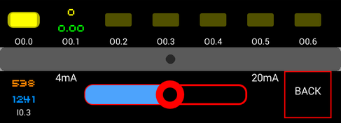
It is also possible to have analog inputs, that is variables with values other than just high and low. Values for these can be set by touching them and then sliding the slider bar that appears.
I/O Manager
The I/O Manager allows you to change the type of component associated with each input or output pin.
NOTATIONS
Notations refers to how switches, contacts, relay coils, etc. in the ladder-logic diagram relate to variables used internally in the PLC to execute its logic. There are two variable syntaxes used in PLC Ladder Simulator:
PLC Notation 1
|
When this is chosen, PLC Ladder Simulator automatically adds 8 input variable, 8 output variables, and 24 virtual variables. The tags (variable names) follow the variable naming standards of a commercial PLC manufacturer.
|
This is the type of notation that the variables will take.
Input variable: I0.1 Output variable: O0.1 Virtual variable: M0.1 |
PLC Notation 2
|
When this option is selected, PLC Ladder Simulator automatically adds again 8 input variables, 8 output variables, and 24 virtual variables. The tags follow a different naming format, that of another commercial PLC manufacturer.
|
This is the type of notation that the variables will take.
Input variable: I:0/1 Output variable: O:0/1 Virtual variable: B3:0/1 |
In both naming conventions the user may change the tags (names) of the variables and add more variables as desired.
OBJECTS OF THE LADDER EDITOR
The Ladder Editor has 47 components that may be used to construct ladder-logic diagrams.
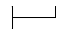
Rung
|
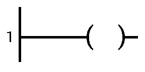
A rung is a horizontal current path that links the input rail to the output rail of a ladder-logic diagram. Since all rungs must have at least one coil on their right side, a new rung is installed in the ladder-logic diagram comes automatically with a coil installed on it.
|
|
Sub-rung
|
A sub-rung is an alternative input path for a rung. It is placed in parallel with an existing rung on the left, input side of the rung. Contacts are then installed on it.
|
|
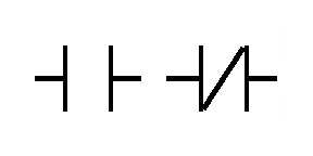
Contacts
|
A contact represents an electrical switch component. A contact acts as an input on a rung. It is associated with an input variable tag.
A normally open (NO) contact does not allow the flow of electricity in its non-activated state. Current can pass through an NO contact only when it is activated or closed. A normally closed (NC) contact allows current to pass when it is inactive. When it is activated, it is opened, and this stops the flow of current. Thus its operation is exactly opposite to that of an NO contact. |
|
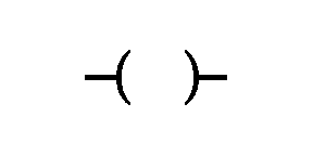
Coil
|
A coil represents an output, usually either a relay coil for starting a machine or an indicator light to show that it is on. It is located on the right side of a rung. A coil is associated with an output variable or a virtual variable.
Whether the coil is on or not depends on whether current reaches it through the contacts, the inputs, on the left side of the rung or sub-rung. Coils associated with output variables,, when activated in a simulation, will show this activation by illuminating in the PCL I/O Interface, described above. The user can choose three different types of coils:
|
|
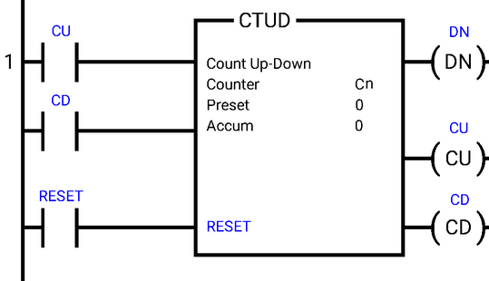
The Counter
|
The counter counts things, namely the number of times the NO switch, associated with the Accumulator (Accum) variable, is closed. It starts at 0 and counts up to a preset value, Preset. When Accum reaches Preset, the output coil, DN for “done”, is set high. There is a second input to the Counter, the Reset. When Reset is set high, Accum is set back to 0 and DN is turned off. There is also a second output from the counter (CU for “counter up”) that goes high whenever Accum is incremented. It can be connected to an indicator to show the operator the incrementing of Accum as things are counted.
One installs the counter into an existing rung. When a counter is installed, two DINT variables are created, one for Preset and one for the Accum. |
|
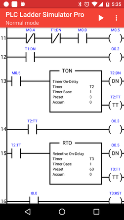
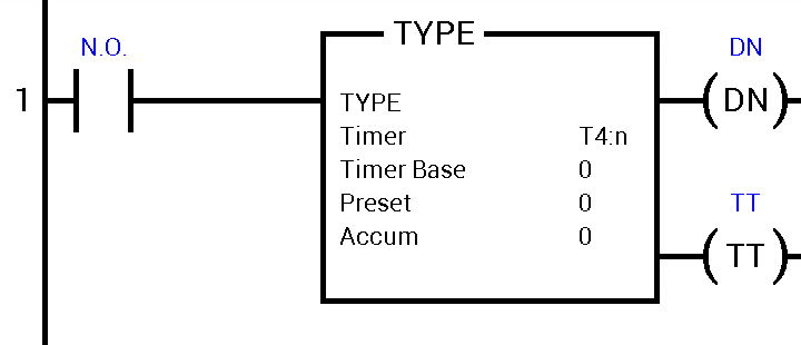
The Timer
|
The timer marks time. It is similar to the counter in that there is an Accum variable to count the seconds that have passed and a Preset variable, which is a preset span of time to be reached before some other process can begin. The timer can be configured to work in three different ways.
|
|
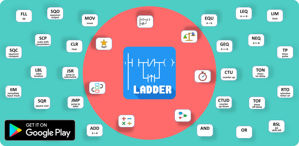
THE OTHER 34 FUNCTIONS
There’s plenty of information on the Internet for the functionality of these functions. You can check these two links (link1, link2) for detailed information on the operation of these functions.
IMPORTAN TIPS:
- EQU
- NEQ
- LES
- LEQ
- GRT
- GEQ
- LIM
- MEQ
- MOV
- BSL
- BSR
- ROL
- ROR
- AND
- OR
- NOT
- XOR
- ADD
- SUB
- MUL
- DIV
- ABS
- SQR
- XYP
- ASN
- ACS
- ATN
- COS
- LN (natural log)
- LOG (base-10 log)
- SIN
- TAN
- SCP
- SCL
IMPORTAN TIPS:
- MOV, SCP, and SCL are the only functions that can read and write analog pins.
- The BSL, BSR, ROR, and ROL functions can make a direct bit shift on the digital output pins. To use them you must select the least significant bit of the output pin in the “Variable (Output – INT - DINT)” section and in the length the number of bits where aims to the most significant bit.
HOW TO USE THE APP
HOW TO USE THE ANALOG INPUT PIN
Follow these steps to read analog data from an analog input pin and move it to a variable in your ladder program:
The analog data of this analog input (AI) will be stored in the INT variable created in 13.
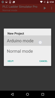
- Create a new project.
- Select a PLC notation.
- Open the I/O Manager from the main menu.
- Click the edit button (pencil).
- Select the input to edit. (With a new project you will have only one input to choose.)
- Select “Analog” as the input type.
- Set the Resolution.
- Select the input range.
- Close the I/O Manager.
- Open the Ladder Editor from the main menu.
- Add the function MOV from “Logic Operation/Move”
- Select the place to locate it. This will create a new rung with an NC switch and the MOV function in it.
- Add an INT variable with any name you like. (We suggest “From AI” to demonstrate MOV.)
- In the “Destination” section of the MOV function select the INT variable created in point 13.
- In the “Source A” section of the MOV select the analog input pin (variable).
- Select OK.
The analog data of this analog input (AI) will be stored in the INT variable created in 13.
HOW TO USE THE ANALOG OUTPUT PIN
Follow these steps to write analog data to an analog output pin:
IMPORTANT: The MOV, SCP, and SCL functions are the only ones that can write onto an analog output pin.
- Create a new project.
- Select a PLC notation.
- Open the I/O Manager from the main menu.
- Click the edit button (pencil).
- Select the output to edit.
- Select “Analog” as the output type.
- Set the Resolution.
- Select the input range.
- Close the I/O Manager.
- Open the Ladder Editor from the main menu.
- Add the function MOV from “Logic Operation/Move”
- Select the place to locate it.
- Add an INT variable named “From AI”.
- In the “Source A” section of the MOV select the variable with the data to write onto the analog output pin.
- Select OK.
IMPORTANT: The MOV, SCP, and SCL functions are the only ones that can write onto an analog output pin.
HOW TO USE A SERVO MOTOR (Arduino mode)
|
In order to use a servo motor you must:
IMPORTANT: The MOV, SCP and SCL functions are the only ones that can write into servo motor pins. |
|
ARDUINO MODE (V1.3)
|
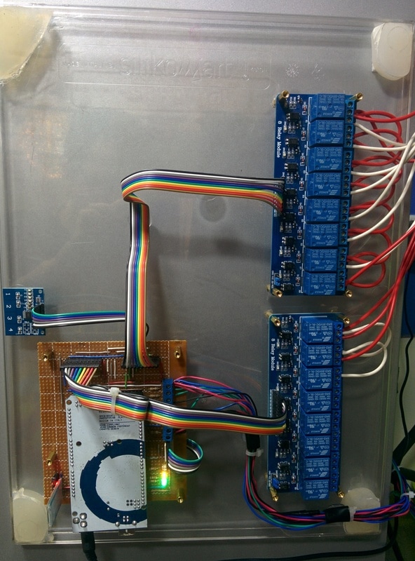
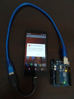
PLC Ladder Simulator PRO features an unique option available in the world and it's the possibility of program an Arduino board with a ladder design using an Android phone. So actually what it does is that transforms an Arduino into a PLC (Programmable Logic Controller).
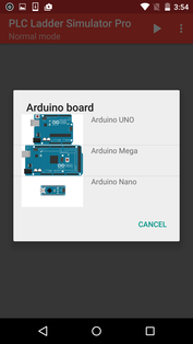
The Arduino mode it's compatible with the Arduino UNO (atmega328), MEGA (atmega2560), NANO (atmega328), DUE, Pro Mini, M5Stack ESP32, MH-ET LIVE ESP32 DevKit and NodeMCU V3 LUA ESP8266. In order to program the board with the PLC Ladder Simulator Pro the Arduino must be already programed with a firmware, this firmware is an Arduino sketch an can be downloaded from this website. The firmware allows the communication between the board and the android, it also executes a ladder interpreter program that runs the ladder design stored in the EEPROM memory of the board. As was mentioned above the ladder design is stored in the EEPROM memory of the Arduino board. It's good to know for the users that according whit the datasheets of the atmega328p and the atmega2560, the memory EEPROM have a total of 100,000 Write/Erase cycles compared with the 10,000 cycles of the FLASH memory. The Flash memory is where the normal Arduino sketch is stored. The operation of this mode is the same as the normal mode, before programming the Arduino board there must be a ladder design. |
IMPORTANT: No refunds for the PRO EDITION will be made beyond 72 hours after its purchase if the problem is compatibility in Arduino mode. The rationale for this is that you can use the free version of PLC Ladder Simulator to test and see if the Arduino is compatible with your version of PLC Ladder Simulator prior to purchasing the PRO version.
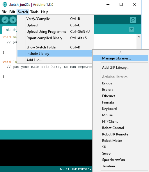
Required Arduino libraries
|
The following steps are not required for the Arduino UNO, NANO and PRO Mini. For the other boards are mandatory.
|
|
BOARDS COMPATIBLE WITH PLC LADDER SIMULATOR
Arduino UNO
|
The characteristics of this board using the PLC Ladder Simulator app are:
|
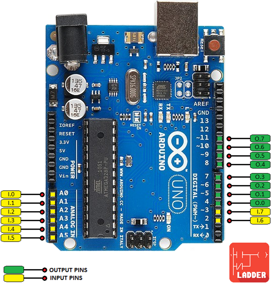
Arduino UNO pinout diagram.
| ||||
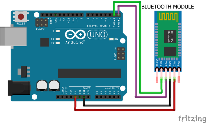
Arduino UNO in Bluetooth connection.
Arduino Mega
|
The characteristics of this board using the PLC Ladder Simulator app are:
|
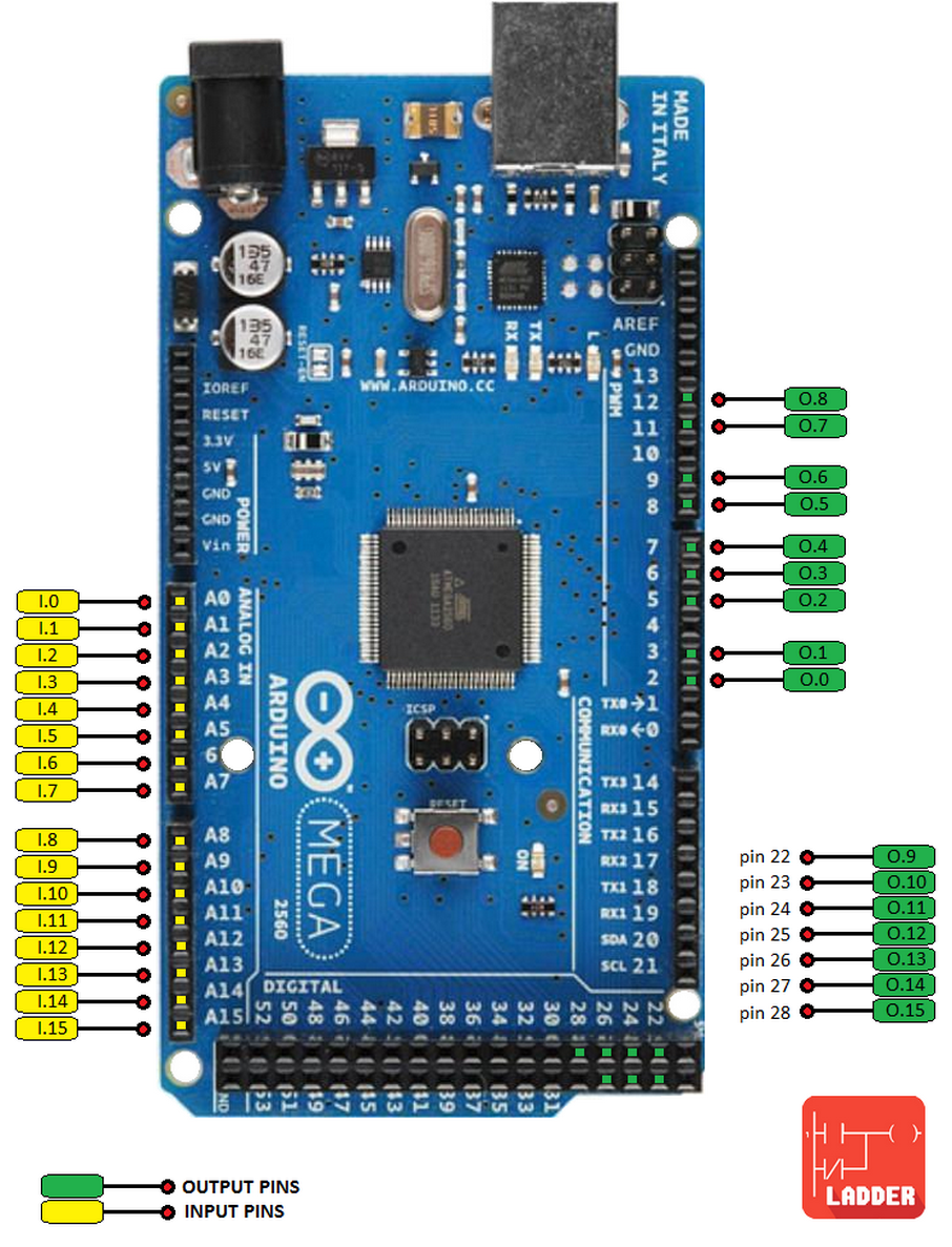
Arduino Mega pinout diagram.
| ||||||||||
Arduino MEGA in USB connection.
Arduino MEGA in Bluetooth connection.
Arduino UNO in LAN connection.
Arduino Nano
|
The characteristics of this board using the PLC Ladder Simulator app are:
|
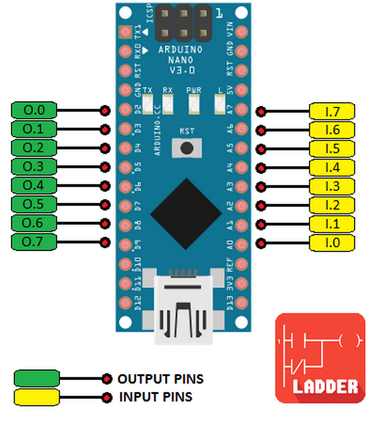
| ||||
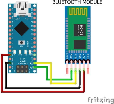
Arduino Nano in Bluetooth connection.
Arduino Pro Mini
|
The characteristics of this board using the PLC Ladder Simulator app are:
|
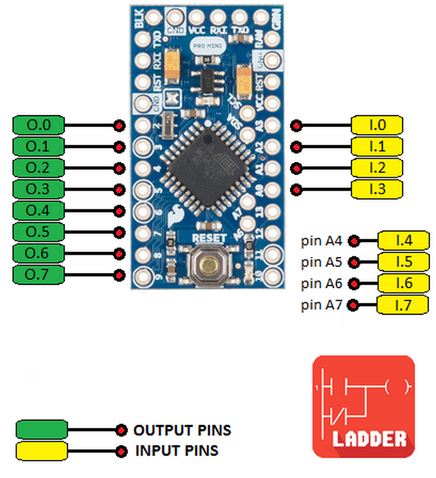
| ||
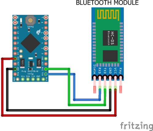
Arduino Pro Mini in Bluetooth connection.
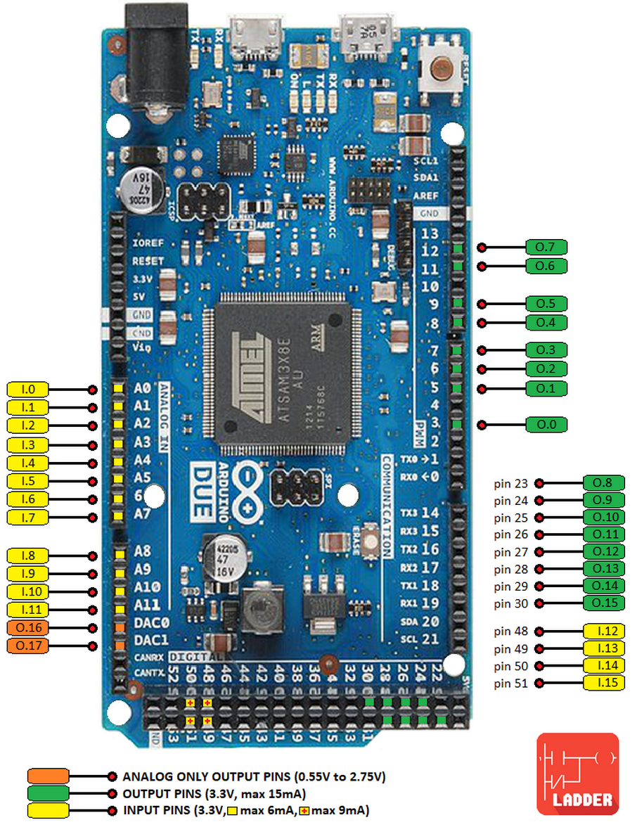
Arduino Due
|
The characteristics of this board using the PLC Ladder Simulator app are:
The Arduino Due it’s not installed by default in the Arduino IDE, here you can find a guide on how to install it in the Arduino IDE. Warning: Unlike most Arduino boards, the Arduino Due board runs at 3.3V. The maximum voltage that the I/O pins can tolerate is 3.3V. Applying voltages higher than 3.3V to any I/O pin could damage the board.
|
| ||||
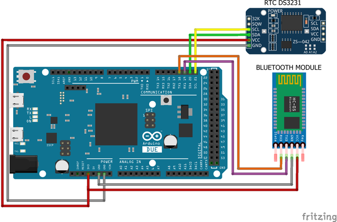
Arduino Due in Bluetooth connection.
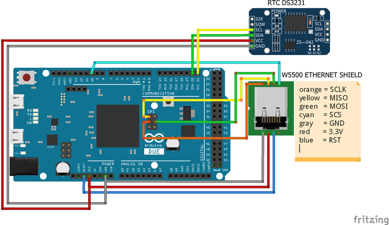
Arduino Due in LAN connection.
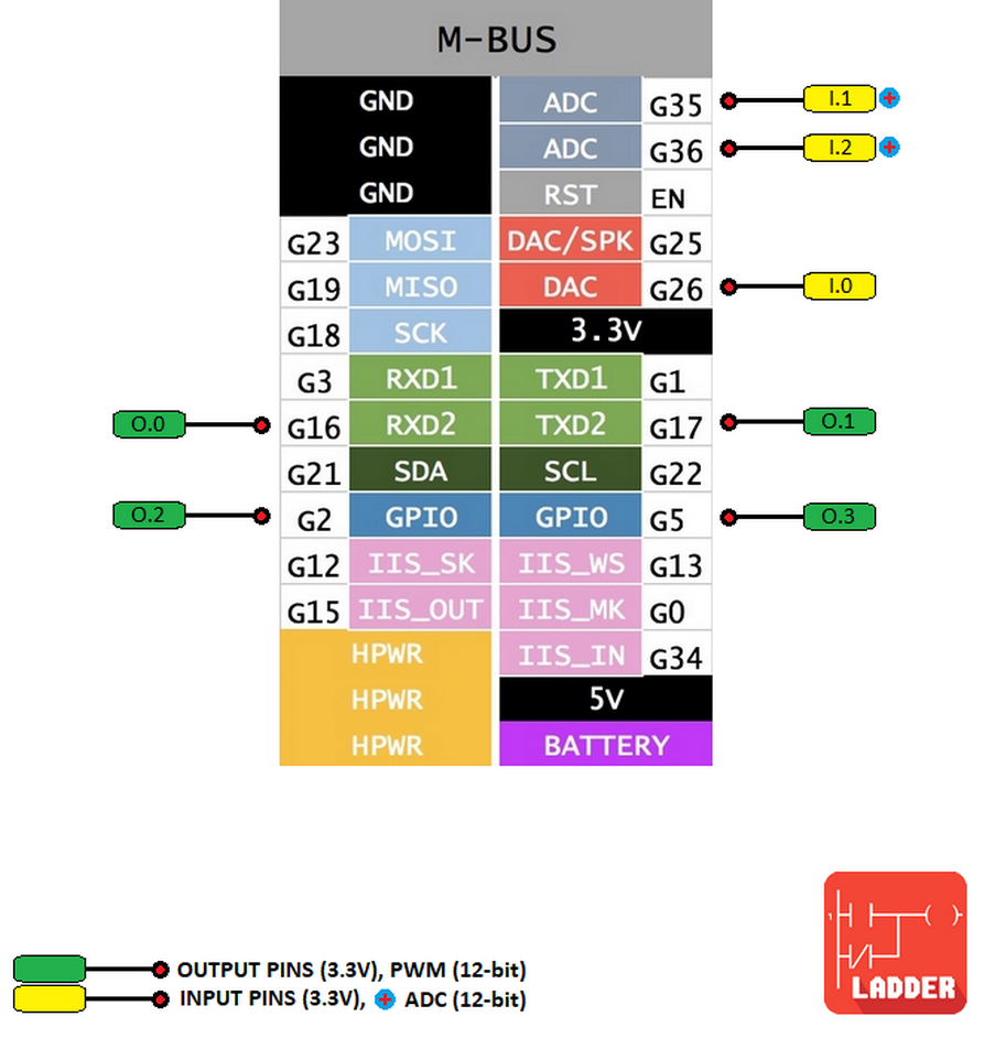
M5Stack ESP32
|
The characteristics of this board using the PLC Ladder Simulator app are:
In order to use this board with the PLC firmware, the Arduino IDE must be configured to work with it, here you can find a guide on how to install the Arduino core for the ESP32. Button A: enables HMI mode. Button C: changes screen display brightness. Warning: This board runs at 3.3V. The maximum voltage that the I/O pins can tolerate is 3.3V. Applying voltages higher than 3.3V to any I/O pin could damage the board.
|
| ||
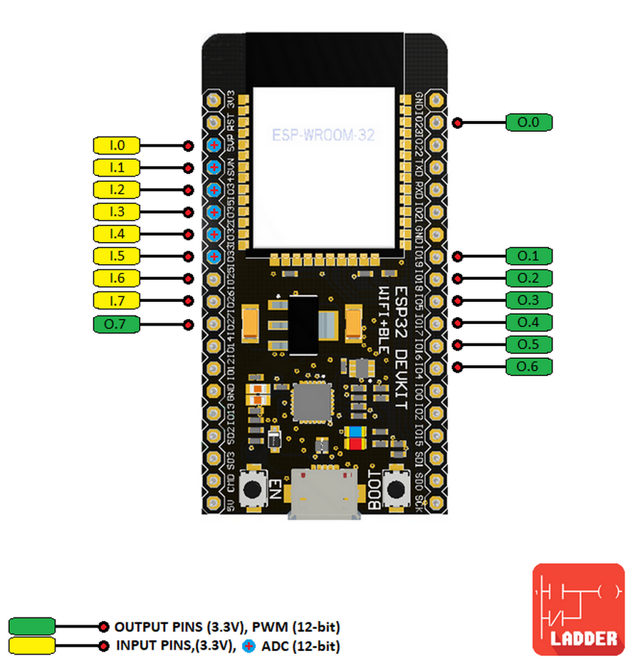
MH-ET LIVE ESP32 DevKit
|
The characteristics of this board using the PLC Ladder Simulator app are:
In order to use this board with the PLC firmware, the Arduino IDE must be configured to work with it, here you can find a guide on how to install the Arduino core for the ESP32. Warning: This board runs at 3.3V. The maximum voltage that the I/O pins can tolerate is 3.3V. Applying voltages higher than 3.3V to any I/O pin could damage the board.
|
| ||
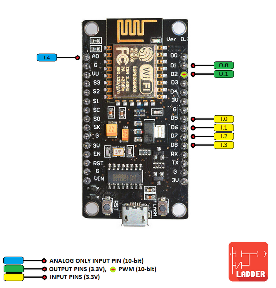
NodeMCU V3 LUA ESP8266
|
The characteristics of this board using the PLC Ladder Simulator app are:
In order to use this board with the PLC firmware, the Arduino IDE must be configured to work with it, here you can find a guide on how to install the Arduino core for the ESP32. Warning: This board runs at 3.3V. The maximum voltage that the I/O pins can tolerate is 3.3V. Applying voltages higher than 3.3V to any I/O pin could damage the board.
|
| ||
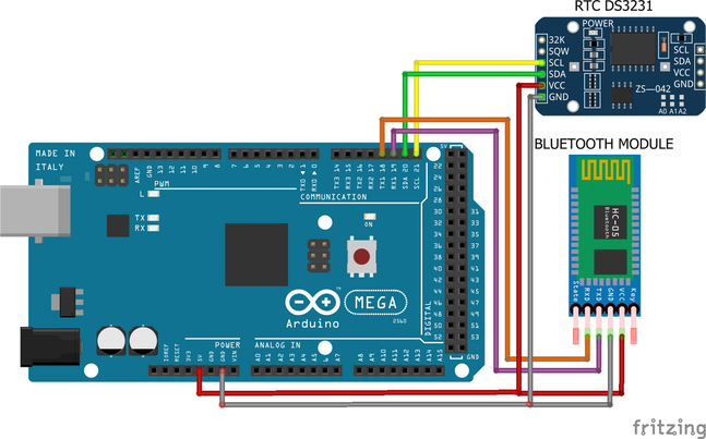
Important points when using a Bluetooth module
- The compatible Bluetooth modules for the moment are the HC-05 and the HC-06, but feel free to test with other modules.
- The Bluetooth module must be configured to work at a baud rate of 9600.
- Connect the RX pin of the BT module to the TX0 pin (TX1 in the NANO) of the Arduino, and the TX pin of the BT module to the RX0 pin of the Arduino.
- Unplug the RX and TX pins of the Bluetooth module before uploading a firmware.
Important points when using an Ethernet module
- Remember to change the ip, gateway and subnet of the "firmware_mega_ethernet_v1.3.ino" file with the data of your LAN before uploading it to the Arduino board.
- The port number for the LAN connection is 23.
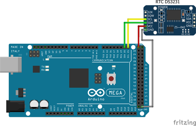
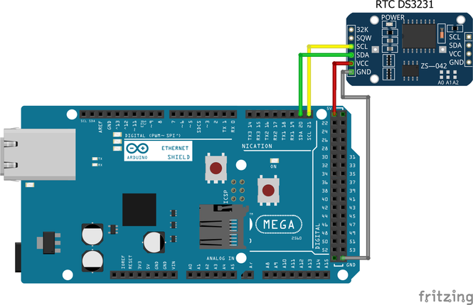
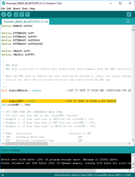
RTC (Real Time Clock)
|
The RTC is a clock that keeps track of the current time, this allows to execute certain actions in the PLC when some variables match a certain date or time. The compatible RTC modules are the DS1307, DS1337 and DS3231.
The DS1307 module only works with 5 volts. The DS1337 and DS3231 can work with 3.3 or 5 volts. It's recommended to use the DS3231 due it can work with all the compatible boards and it have more accuracy in comparison to the other modules. The RTC feature can be activated by setting the “enabledRTC” variable to true in the firmware sketch before it’s uploaded into the board. The RTC feature is enabled by default for the M5Stack ESP32, MH-ET LIVE ESP32 DevKit and NodeMCU V3 LUA ESP8266. This boards have a built-in RTC that is updated every time the board is power-up, but they required to be connected to the internet to do so. For the other boards the RTC is updated with the current time when the ladder design is uploaded from the Android device. The RTC can be updated to the current time manually by using the app, this option is available in Arduino mode, just connect the board to the Android device and then press the “Update RTC” option from the menu. Set your time zone GMT in the “clockGMT” variable before the firmware is uploaded to the Arduino board, a list of zones and GMT is available in the firmware. |
Enable RTC module in firmware sketch.
|
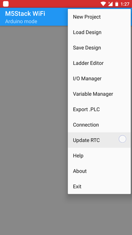
Manual RTC update.
Set WiFi on board
The M5Stack ESP32, MH-ET LIVE ESP32 DevKit and NodeMCU V3 LUA ESP8266, come with integrated WiFi support, no extra modules are required to enabled the WiFi feature.
To set and enabled the WiFi feature the network name and the password must be entered in the “ssid” and “password” variables.
To set and enabled the WiFi feature the network name and the password must be entered in the “ssid” and “password” variables.
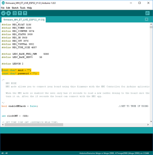
Set WiFi in firmware sketch.
|
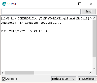
To determine the IP address assigned to the board, connect the board to the PC, open the Arduino IDE, select the serial port of the board, open the “Serial monitor”, set it at 115200 bauds and reset the board. The assigned IP address will be displayed. In the M5Stack ESP32 the assigned IP address will be displayed in the display screen when the board it’s booting. |
|
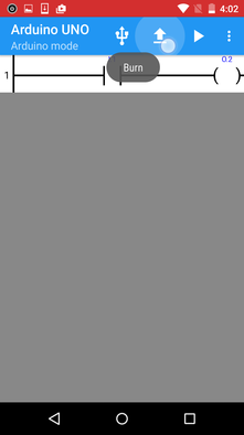
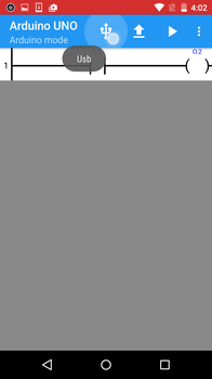
How to use and upload the PLC design over USB
Important: In the new version of the firmware it’s not required to reset the board once is connected to the Android device, the feature of 8 seconds of the blinking led L (pin 13 ) was removed, the board can be programmed any time after it’s connected to the Android device.
|
The process of making a design in this mode is:
|
'>
Step 4.
Step 6.
Step 11.
Step 13.
Step 17.
|
Step 5.
Step 7.
Step 12.
Step 16.
|
How to upload the PLC design over Bluetooth
Important: In the new version of the firmware it’s not required to reset the board once is connected to the Android device, the feature of 8 seconds of the blinking led L (pin 13 ) was removed, the board can be programmed any time after it’s connected to the Android device.
How to upload the PLC design over LAN
CAN’T BURNT THE DESIGN INTO THE ARDUINO?
Check this possible solutions:
- Close the app, turn off your Android device and turn it on again (hard shutdown).
- Install and use the last version of the Arduino IDE from https://www.arduino.cc/ (V 1.8.4 or later)
- Upload the last Arduino sketch (firmware) of PLC Ladder Simulator available in this site into the Arduino board.
- It’s very important to open the app with the pop-up message that appears once Arduino board is connected to the Android device, if the pop-up message is canceled and the app is open manually, this will not recognize the Arduino board.
- Enable the USB Debugging setting in the Android device, sometimes this fix the issue.
- Don’t use an Arduino clone with the CH340 USB chip, will not work.
- Xiaomi phones will not detect the Arduino board over USB. Use Bluetooth or LAN alternative connection.
- Use the PLC Loader for PC.
THE ANDROID DEVICE DOES NOT RECOGNIZE THE ARDUINO BOARD?
If the Arduino board does not turn on and doesn't pop up a message to open the app when is connected to the Android device with the OTG USB cable, the following steps could fix it:
- Power up the Arduino board with an external power supply.
- Connect the Android device to a PC.
- Wait 20 seconds.
- Disconnect the Android device from the PC.
- Plug the Arduino board to the Android device with the USB OTG cable.
- Android should recognize the Arduino board by displaying a pop-up message once is plugged.
- If nothing happened when the Arduino board is plugged to the Android device, turn the off the Android device with a hard shutdown and try again from the point 2.
HMI Controller for Arduino app
|
The HMI Controller for Arduino is an application for the Android OS that allows you to connect your Arduino board with your Android device in an easy way, it can be connected over Bluetooth or LAN (Local Area Network).
Make your own customizable HMI in the app without the need of a computer, you can select from eight different objects (widgets): button, switch, led, display 7-segments, numeric display, bar indicator, slider and graph. PLC Ladder Simulator it's compatible with the HMI Controller for Arduino app when using it in the Arduino mode, this is the best complement for your PLC Arduino projects. For more information on how to use HMI Controller for Arduino go to the main page of the app. |
To enable the HMI feature in the Arduino UNO, NANO and PRO Mini, the board should be uploaded with a PLC firmware with HMI enabled. Here you can find some videos on how to use the HMI app with the Arduino mode.
- Arduino UNO with Bluetooth connection -> firmware_uno_hmi_v1.1.ino
- Arduino NANO with Bluetooth connection -> firmware_nano_hmi_v1.1.ino
- Arduino PRO Mini with Bluetooth connection -> firmware_pro_mini_hmi_v1.0.ino
|
| ||||||
To enable the HMI feature for the Arduino DUE, Arduino MEGA, the NodeMCU V3 ESP8266 and the MH-ET LIVE ESP32, you should set to “true” the “enableHMImode” variable in the firmware sketch before it’s uploaded into the board. When the HMI mode is enabled the user only has 15 seconds to load a new ladder design to the board once the board is turn it on. After the 15 seconds the board can connect to the HMI app.
For the M5Stack ESP32 the HMI mode is enabled by pressing for a few seconds the A button. When is active the “HMI” word in red will be shown.
For the M5Stack ESP32 the HMI mode is enabled by pressing for a few seconds the A button. When is active the “HMI” word in red will be shown.
Important: The port number for the LAN connection is 23.
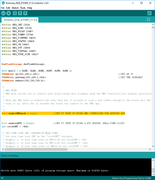
"enableHMImode" variable in the firmware sketch.
The relation between the HMI widgets and the PLC variables are this:
The variables of type DINT and REAL are not available in the Arduino UNO, NANO and PRO Mini for the HMI mode.
When using the HMI app in "PLC Ladder App Mode" the users doesn’t need to use any of the HMI app commands in order to manage the communication, the PLC firmware in the Arduino is in charge of the synchronization and management of the communication.
- Button: Output, virtual(bool)
- Switch: Output, virtual(bool)
- Slider: INT, DINT, REAL.
- Led: Input, Output, Virtual(bool)
- Display 7 segments: INT, DINT, REAL.
- Numeric Display: INT, DINT, REAL.
- Bar Indicator: INT, DINT, REAL.
- Graph: INT, DINT, REAL.
The variables of type DINT and REAL are not available in the Arduino UNO, NANO and PRO Mini for the HMI mode.
When using the HMI app in "PLC Ladder App Mode" the users doesn’t need to use any of the HMI app commands in order to manage the communication, the PLC firmware in the Arduino is in charge of the synchronization and management of the communication.
|
|
|
PLC Loader (v1.0)
|
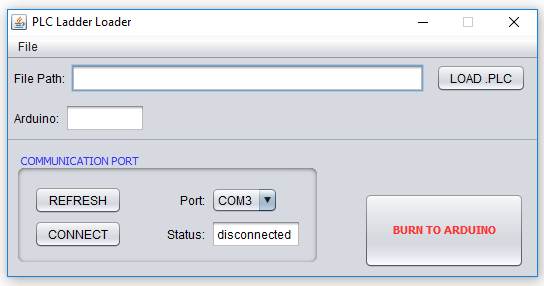
The PLC Loader is a tool that allows to upload the ladder design to the Arduino board using a PC, this software is useful for users that have issues trying to upload the ladder design into the Arduino board directly from the Android device.
After the .PLC file is exported, the file is saved inside the "Arduino mode" folder located in the "PLC Data" folder of the Android device. This feature is compatible only with Arduino UNO, NANO and MEGA. Note 1: PLC Loader is compatible only with Windows. Note 2: Compatible only with JRE (Java Runtime Environment) version 8u144.
|
| ||||
Firmwares
|
| ||||
|
| ||||
|
| ||||
|
| ||||
|
| ||||
| firmware_m5stack_v1.0.zip |
© 2017 Sergio Daniel Castañeda N . All rights reserved.
